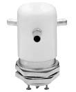
Features high frequency load voltage, up to 50A under continuous DC, small size, low and stable contact resistance, low power in RF circuit,
Two optional installation methods, flange type and bolt type, bolt type or welding type high-voltage connector, simple wiring, replaceable coil, make the product function diversified, meet or exceed mil-r-83725 standard. For load switch application, please consult the factory!
Specification No
GT23
GT23A
GT23B
Contact configuration
1C
1A
1H
Test voltage (DC or 50Hz AC peak)
Test Voltage (DC or AC 50Hz Peak)kV
seventeen
fifteen
fifteen
Rated operating voltage (peak)
Rated Operating Voltage(Peak) kV
DC or AC 50Hz
fifteen
twelve
twelve
AC2.5MHz
twelve
ten
ten
AC16MHz
ten
eight
eight
AC32MHz
seven
four
four
Rated carrying current (effective value)
Rated Carrying Voltage(RMS) A
DC or AC 50Hz
forty
thirty-five
thirty-five
AC2.5MHz
thirty
twenty-five
twenty-five
AC16MHz
seventeen
fifteen
fifteen
AC32MHz
ten
ten
ten
Contact resistance (Ω)
zero point zero two five
zero point zero three
zero point zero three
Contact capacitance (PF)
Between disconnected contacts
Beteween Open Contacts
zero point five
zero point eight
zero point eight
Between contact and housing
Open Contacts to Ground
one
one
one
Operate time max. (MS)
fifteen
ten
ten
Release time max. (MS)
nine
ten
ten
Temperature range of temp (℃)
-55~+125
-55~+125
-55~+125
Shock level, 11ms 1/2sine (peak G's)
fifty
thirty
thirty
Vibration, peak 10g's (Hz)
55~500
55~500
55~500
Expected mechanical life( × 106)
one
one
one
Nominal weight (g)
eighty-five
eighty-two
eighty-two
Coil parameter
Rated voltage DC (V)
twelve
twenty-four
twenty-six point five
one hundred and fifteen
Maximum pull in voltage max. DC (V)
eight
15-16
15-16
eighty
Release voltage dropout voltage Min.DC(V)
0.5-5
1-10
1-10
5-50
Coil resistance (Ω± 10%)
forty-eight
one hundred and eighty
two hundred and fifty
two thousand and nine hundred
*The above data are measured at 25 ℃ and sea level
Model selection instructions relay user instructions
GT23 A 12Vdc S F
contact form
A=SPST-NO
B=SPST-NC
C = SPDT
Coil voltage
Blank =24vdc
26.5V=26.5Vdc
12V=12Vd
115V=115Vdc
High voltage connector
S= welded
W= bolted
install
F= flange type
P= bolted
When ordering relays, please indicate the model with coil voltage as shown above, and the coil voltage will appear on the relay model.